PROCESSORS
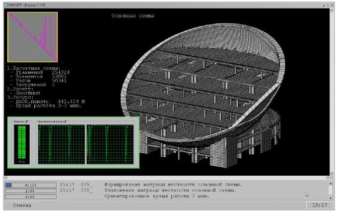 1. Parallel calculation on multicore computers. 1. Parallel calculation on multicore computers.
It is possible to make parallel calculations for solving the systems of linear equations and dynamic problems (spectrum analysis) on 2, 4 and 8-core computers. On two-core computers, systems of linear equations are solved 1,5 times faster, dynamic problems are solved 1,8 times faster.
2. Creep analysis according to Eurocode. Stress-strain state of elements of the structure under short-term loads is considered as initial state for creep analysis.
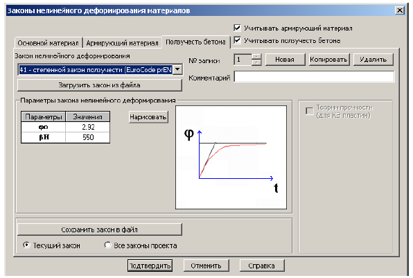 It is necessary to define required time periods in days after which analysis algorithm determines the changes in stress-strain state caused by creep of concrete – redistribution of stresses between reinforcement and concrete in sections of elements, redistribution of forces between elements, increase of displacements, etc. It is necessary to define required time periods in days after which analysis algorithm determines the changes in stress-strain state caused by creep of concrete – redistribution of stresses between reinforcement and concrete in sections of elements, redistribution of forces between elements, increase of displacements, etc.
This feature provides more options for computer simulation of life cycle of the structure. It also helps the user to evaluate behaviour of the structure during its maintenance.
3. Geometric nonlinearity in DYNAMICS plus special solver.
Dynamic analysis of geometrically nonlinear systems — separate cables, guy structures, membranes, structures with large displacements, etc. This feature helps the user to completely simulate behaviour of arbitrary structures under dynamic loads.
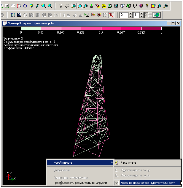
4. Stability. Analysis of sensibility.
Degree of responsibility (sensibility) of every element for buckling of the whole structure is determined. Degree of responsibility may be obtained in colour and numerical presentation. This procedure enables the user to find out which elements should be designed more conservatively or to which elements it is necessary to pay more attention in analysis of progressive fracture.
5. Dynamic factor and step-type analysis in disassemblage. This procedure is important because of the following reason: if a load or an element is deleted at the stage of disassemblage, then the rest part of the structure should be analysed on deleted load or on forces from deleted element applied with the opposite sign. Such analysis in a number of cases should be performed in a nonlinear statement and therefore it is necessary to use the step-type method for this analysis. If a load or an element is deleted unexpectedly, then correspondent load from them should be multiplied by dynamic factor. This factor provides correct calculations for stability analysis in cases of progressive fracture when it is necessary to analyse the structure on sudden removal of one or several elements.
6. Dynamics and stability in ASSEMBLAGE solver.
Dynamic analysis and stability analysis of structure may be performed. The stress-strain state of the structure that takes account of its assemblage is considered as initial state in these analyses.
7. Perfectly rigid bodies in stability problems and geometrically nonlinear problems. This option enables the user of LIRA 9.6 to completely consider rigid bodies in all kinds of problems: linear and nonlinear problems, linear and nonlinear dynamics, stability problems, assemblage.
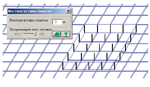
8. Offsets out-of-plane in plate elements.
It helps the user to define slabs of different thickness, capitals, etc.
| 9. Account of orthotropy in plates and solids. Material properties with different physical-mechanical parameters in various directions may be taken into account. | 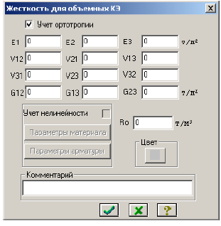 | 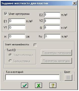 |
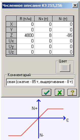 10. One-node and two-node special finite elements with limit forces. Special 1-node and 2-node finite elements (nonlinear analogues of FE 51, 55, 56) are mentioned to simulate connections that have different limit forces of different sign. Moreover, these finite elements consider unloading paths that may not coincide with loading one. 10. One-node and two-node special finite elements with limit forces. Special 1-node and 2-node finite elements (nonlinear analogues of FE 51, 55, 56) are mentioned to simulate connections that have different limit forces of different sign. Moreover, these finite elements consider unloading paths that may not coincide with loading one.
11. Solver window is optimized for wide-screen displays.
LIR-VISOR
1. Analysis results are converted to loads.
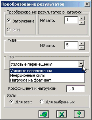
Added option: analysis results are converted to a separate load case in input data. This option considerably simplifies many time-consuming procedures of defining input data. For example, make more exact calculation of the fragment of structure with results (displacements, reactions) of preliminary analysis of structure with large-scale discretization. Option to convert inertial forces from dynamic analysis into initial loads provides the user with more convenient way to analyse physically and geometrically problems by these loads.
2. Import of analysis results from design modules.
2.1 Determined rolled shapes are imported from LIR-STC module to LIR-VISOR module. This option enables the user to replace shapes specified earlier with shapes determined in LIR-STC module and analyse the problem once more. This option simplifies and speeds up optimization procedure for element sections under specified loads.
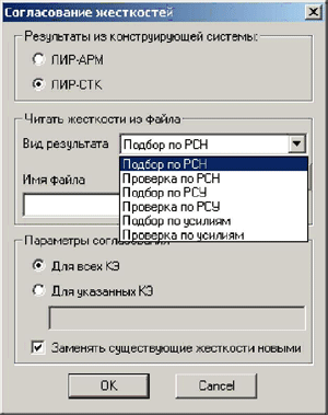 2.2 Areas of determined reinforcement (in plates and bars) are imported from LIR-ARM module. This option significantly simplifies the process of defining material parameters in analyses of RC structures as physically nonlinear systems. With the help of this option and DCF unification options in element groups the engineer could easily convert the model from linear to nonlinear one. In this case the program automatically generates all necessary stiffness parameters (class of concrete and reinforcement), areas of reinforcement and distances to reinforcement from element edges. 2.2 Areas of determined reinforcement (in plates and bars) are imported from LIR-ARM module. This option significantly simplifies the process of defining material parameters in analyses of RC structures as physically nonlinear systems. With the help of this option and DCF unification options in element groups the engineer could easily convert the model from linear to nonlinear one. In this case the program automatically generates all necessary stiffness parameters (class of concrete and reinforcement), areas of reinforcement and distances to reinforcement from element edges.
3. Parameters of design model (loads, hinges, offsets, orthotropy axes of materials and unification axes specified in FE) may be saved when operations with transformation of FE mesh are performed.
4. New service options:
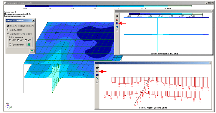
4.1 Diagrams are presented along arbitrary sections of plates.
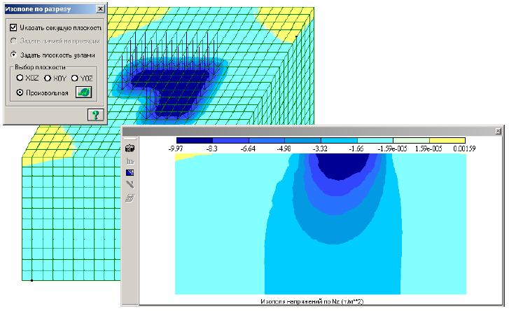
4.2 Contour plots are presented along arbitrary sections of solids.
4.3 Accelerations from wind pulsation are visualized in all nodes of the model (mosaic plot).
4.4 Forces in special FE are presented in graphical output of analysis results.
4.5 Various formats and precision for numerical values in tables, various fonts for working window.
4.6 All DCF groups (design complete, design live, normative complete and normative live) may be printed in standard and interactive tables.
4.7 Max and min values are presented in colour in numerical columns of interactive tables.
5. New options that considerably simplify the procedure of defining input data:
 5.1 FE of zero stiffness may be defined to collect loads on other elements. 5.1 FE of zero stiffness may be defined to collect loads on other elements.
5.2 Design model is imported from several data formats, such as MSH (files with description of FE mesh), STL (files with description of 3D-stereolithography models), OBJ (files with description of 3D geometry models).
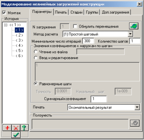
5.3 Dialog boxes for defining parameters for assemblage tables and simulation of nonlinear load cases are united into one dialog.
6. Options with loads:
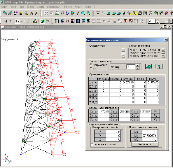
- determine total loads on selected elements and nodes along all directions;
- determine centre of applied loads;
- calculate moments of forces relative to the specified point.
With these options the user could easily replace large number of different loads with several equivalent ones in order to simplify input data. It is also possible to determine values of stabilizing and overturning moments, etc.
LIRA - SOIL system
7. The following options simplify the procedure of creating design models with account of soil properties:
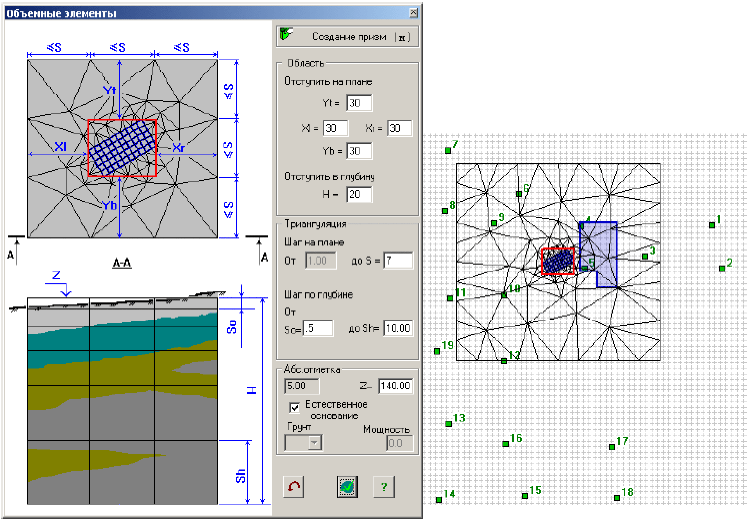
7.1 Soil mass is generated from physically nonlinear 3D FEs of soil. It is possible to export these FEs to LIR-VISOR module with specified stiffnesses and loads from neighbouring structures.
7.2 Soil mass is generated from physically nonlinear 2D elements of soil according to specified geology. It is possible to export these FEs to LIR-VISOR module with specified stiffnesses and loads from neighbouring structures.
8. New convenient mode for presentation of vertical stress diagrams in soil.
9. Unite Loads command enables the user considerably reduce time for calculation of subgrade moduli.
LIR-ARM
10. The work with large models become more easier because of multiple threads executed on multiprocessor systems. Time for analysis is reduced by 50-70%.
11. Unified reinforcement for physically nonlinear FE (see LIR-VISOR, section 2.2) is exported to LIR-VISOR module.
LIR-SRS
12. Enhanced option: graphic interface that demonstrates modern features of Microsoft;
13. Added option: possibility to generate steel tables with arbitrary shapes that may be used in LIR-KM module.
LIR-STC
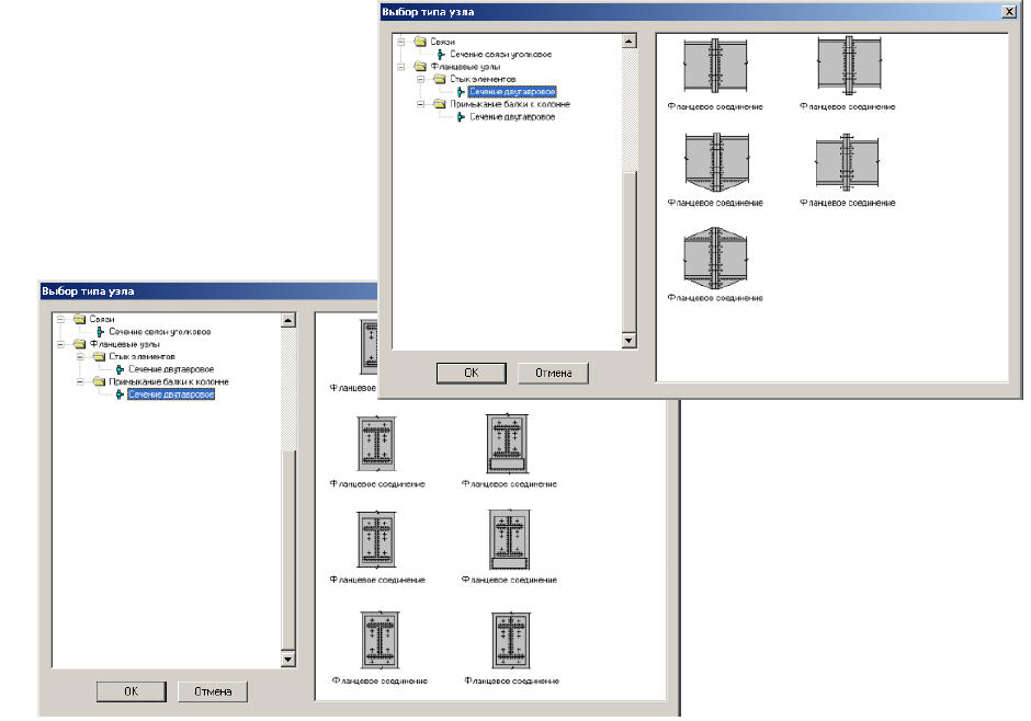
14. Added option: new joints of steel structures — rigid joints: beam-to-column connections, beam-to-beam connections, etc.
LIR-KM
15. 2D drawings are generated with or without hidden lines.
16. LIR-KM objects are edited in 2D mode where unacceptable changes of Z-coordinate are ignored.
17. Shapes of arbitrary cross-sections may be used.
18. New joints available in LIR-STC module may be automatically designed and drawn.
| 
 Version History


